• Home
  • Field Instruments
    • Flow Measurements
      • Flow Electromagnetic
      • Flow Ultrasonic
    • Level Measurements
      • Level Radar
      • Level Ultrasonic
      • Remote Monitor
    • Positioner
      • Electromagnetic Valve Positioner
    • Pressure Measurements
      • Pressure Transmitter
    • Process Controllers
    • Process Protections
    • Supplementory Components
    • Temperature Measurements
      • Head Transmitter
      • Rail Transmitter
    • Weighing Technology
      • Stand Alone Integrator
      • Weighing Electronic
  • Factory Automation
    • S7-1200
    • S7-1500
    • S7-300
  • Power Supplies
    • Logo! Power
    • Sitop Smart
  • Services
  • About
  • Contact

PT. Adika Mitra Sehati

Serving with lates technologies, great value for money, above industrial standards requirements


    P_ST70_XX_02242i
    S7-300
    • The modular mini PLC system for the low and mid-performance ranges
    • With comprehensive range of modules for optimum adaptation to the automation task
    • Flexible use through simple implementation of distributed structures and versatile networking
    • User-friendly handling and uncomplicated design without a fan
    • Can be expanded without problems when the tasks increase
    • Powerful thanks to a range of integrated functions


    S7-300F
    • Failsafe automation system for plants with increased safety requirements for production technology
    • Based on S7-300
    • Additional ET 200S and ET 200M distributed I/O stations complete with safety-related modules can be connected
    • Safety-related communication via PROFIBUS DP with PROFIsafe profile
    • Standard modules can be used in addition for non-safety-relevant applications


    Catalog ST 70:

    You can also find information about SIMATIC S7-300 in Catalog ST 70:

    http://www.automation.siemens.com/salesmaterial-as/catalog/en/simatic-st70-chap05-english-2015.pdf


    Application

    S7-300

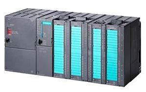
    The SIMATIC S7-300 is the modular mini PLC system for the low-end and mid performance ranges.

    The modular and fan-free design, simple implementation of distributed structures, and convenient handling make the SIMATIC S7-300 the cost-effective and user-friendly solution for the most diverse tasks in the low-end and mid performance ranges.

    Application areas of the SIMATIC S7-300 include:

    • Special machinery,
    • Textile machinery,
    • Packaging machinery,
    • General mechanical equipment manufacture,
    • Controller building,
    • Machine tool manufacture,
    • Installation systems,
    • Electrical/electronics industry and the skilled trades.


    Several performance-graded CPUs and a comprehensive range of modules with a host of user-friendly functions allow you to use only those modules necessary for your application. In the case of task expansions, the controller can be upgraded at any time by means of additional modules.

    The SIMATIC S7-300 is universal in use:

    • Maximum suitability for industry thanks to high electromagnetic compatibility and high resistance to shock and vibration.


    S7-300F

    The SIMATIC S7-300F fail-safe automation system is used in plants with increased safety requirements. It controls processes where immediate shutdown presents no danger to personnel or the environment.

    The S7-300F meets the following safety requirements:

    • Requirement class AK 1 to AK 6 in accordance with DIN V 19250/DIN V VDE 0801
    • Safety requirement class SIL 1 to SIL 3 in accordance with IEC 61508
    • Category 1 to 4 in accordance with EN 954-1


    In addition, standard modules can be used in the S7-300F as well as the fail-safe modules. This makes it possible to establish a fully integrated control system for a plant where non-safety related tasks and safety-related tasks co-exist. The overall plant is configured and programmed with the same standard tools.


    Design

    S7-300

    General

    The S7-300 automation system is modular in design. It has a comprehensive range of modules that can be combined individually.

    A system includes the following:

    • A CPU:
      Different CPUs are available for different performance ranges, including CPUs with integral inputs/outputs and the corresponding functions, as well as CPUs with integral PROFIBUS DP, PROFINET and point-to-point interfaces.
    • Signal modules (SMs) for digital and analog inputs/outputs.
    • Communications processors (CPs) for bus connection and point-to-point connections.
    • Function modules (FMs) for high-speed counting, positioning (open-loop/closed-loop) and PID control.


    The following can also be used depending on requirements:

    • Load power supply (PS) for connecting the SIMATIC S7-300 to a supply voltage of 120/230 V AC.
    • Interface modules (IMs) for connecting the central controller (CC) and expansion units (EUs) in multi-tier configurations.
      The SIMATIC S7-300 can be operated with up to 32 modules distributed across the CC and 3 EUs. All modules can be operated in enclosures and without fans.
    • SIPLUS modules for extended environmental conditions:
      suitable for temperature range -25 to +60 °C, and higher humidity, condensation and frost loads. Can be used direct on vehicles or outside building in an IP20 cabinet protected against direct sunlight and rainwater/spray water. Air-conditioned cabinet and IP65 housing not required.


    Design

    Simple design makes the S7-300 flexible and service-friendly:

    • Module mounting:
      Simply hang the modules on the mounting rail, swing them into place and screw into position.
    • Integral backplane bus:
      The backplane bus is integrated into the modules. The modules are connected via bus connectors plugged into the rear of the housings.
    • Simple replacement of the modules with mechanical key coding:
      Only the fixing screw of the modules has to be unscrewed to replace the module. Wired front connectors are easy to release by pressing on the locking mechanism. The front connector coding prevents connection of the wired front connector to the wrong module type.
    • Field-proven connections:
      Screw-type, spring-loaded or insulation-displacement front connectors are offered for the signal modules.
    • TOP Connect:
      This offers pre-assembled wiring with 1-core to 3-core connections and screw-type or spring-loaded terminals. Alternative to wiring direct on the signal module.
    • Defined installation depth:
      All connections and connectors are recessed into the modules and protected and covered by front doors. All modules thus have a defined installation depth.
    • No slot rules:
      Signal modules and communications processors can be connected in any way without restrictions. The system configures itself.


    Expansion

    If users require more than 8 slots SM, FM or CP modules for their automation tasks, the S7-300 (except CPU 312 and CPU 312C) can be expanded:

    • Max. 32 modules on CC and 3 EUs:
      In total, a maximum of 3 expansion units (EUs) can be connected to the central controller (CC). Eight modules can be connected to each CC/EU.
    • Connection via interface modules:
      Each CC/EU has its own interface module. It is always plugged into the slot next to the CPU on the CC, and it handles communication with the EUs autonomously.

      • Expansion via IM 365:
        1 EU, distance max. 1 m; supply voltage is also transferred.
      • Expansion via IM 360/361:
        3 EUs, max. distance between CC and EU and between EU and EU, 10 m in each case.
    • Physically separate installation:
      The individual CCs/EUs can also be installed at greater distances from each other. Distance between two neighboring CC/EU or EU/EU: max. 10 m.
    • Flexible mounting options:
      The CCs/EUs can be mounted horizontally or vertically. They can thus adapt optimally to the available space.


    Communication

    The S7-300 has different communication interfaces:

    • Communications processors for connecting to the bus systems AS-Interface, PROFIBUS and PROFINET/Industrial Ethernet.
    • Communications processors for point-to-point connections.
    • Multipoint interface (MPI ), integrated into the CPU;
      the low-cost solution for simultaneous connection of PGs/PCs, HMI systems and other SIMATIC S7/C7 automation systems.


    Process communication via PROFIBUS DP

    The SIMATIC S7-300 is connected to the PROFIBUS DP bus system via a communications processor or the CPUs with integral PROFIBUS DP interface. The CPUs with PROFIBUS DP master/slave interface enable distributed automation configurations with high speed and simple handling.

    The distributed I/O via PROFIBUS DP is treated just like a centralized I/O from the user’s perspective (same configuring, addressing and programming).

    The following can be connected as masters:

    • SIMATIC S7-300
      (via CPUs with PROFIBUS DP interface or PROFIBUS DP CPs)
    • SIMATIC S7-400
      (via CPUs with PROFIBUS DP interface or PROFIBUS DP CPs)
    • SIMATIC C7
      (via C7 with PROFIBUS DP interface or PROFIBUS DP CPs)
    • SIMATIC S5-115U/H, S5-135U and S5-155U/H with IM 308
    • SIMATIC 505


    For performance reasons, no more than 2 masters must be connected on one line.

    The following can be connected as slaves:

    • ET 200 distributed I/O devices
    • S7-300 via CP 342-5
    • CPU 313C-2 DP, CPU 314C-2 DP, CPU 314C-2 PN/DP, CPU 315-2 DP, CPU 315-2 PN/DP, CPU 317-2 DP, CPU 317-2 PN/DP and CPU 319-3 PN/DP
    • C7-633/P DP, C7-633 DP, C7-634/P DP, C7-634 DP, C7-626 DP, C7-635, C7-636
    • Field devices


    Although PG/PCs with STEP 7 or OPs are masters on the bus, they only use the MPI functions that also run in part via PROFIBUS DP.

    Process communication via PROFINET IO

    The SIMATIC S7-300 is connected to the PROFINET IO bus system via a communications processor or the CPUs with integral PROFINET interface. The CPUs with PROFINET interface enable distributed automation configurations with high speed and simple handling.

    The distributed I/O via PROFINET IO is treated just like a centralized I/O from the user’s perspective (same configuring, addressing and programming).

    The following can be connected as IO controllers:

    • SIMATIC S7-300
      (via CPUs with PROFINET interface or PROFINET CPs)
    • SIMATIC ET 200
      (via CPUs with PROFINET interface)
    • SIMATIC S7-400
      (via CPUs with PROFINET interface or PROFINET CPs)


    The following can be connected as IO devices:

    • ET 200 distributed I/O devices
    • ET 200S IM151-8 PN/DP CPU, ET 200pro IM154-8 PN/DP CPU
    • SIMATIC S7-300
      (via CPUs with PROFINET interface or PROFINET CPs)
    • Field devices


    Process communication via AS-Interface

    The S7-300 has a suitable communications processor (CP 342-2) for connecting field devices (AS-Interface slaves) for the AS-Interface-Bus.

    For additional information, see Communications processors.

    Data communication via CP or integral interface (point-to-point)

    Point-to-point connections can be conveniently and at low cost via the CP 340/CP 341 communications processors or the integral interface of the CPU 313C-2 PtP or CPU 314C-2 PtP. Different protocols with the three physical transmission media are available:

    • 20 mA (TTY) (CP 340/CP 341 only)
    • RS 232C/V.24 (CP 340/CP 341 only)
    • RS 422/RS 485


    The following can be connected:

    • SIMATIC S7 and SIMATIC S5 automation systems and non-Siemens systems
    • Printers
    • Robot controls
    • Scanners, barcode readers, etc.

    Special blocks are included in the scope of supply of the manuals for the communication functions.


    Data communication via multipoint interface (MPI)

    The multipoint interface (MPI) is a communication interface integrated into the CPUs of the SIMATIC S7-300. It can be used for simple networking.

    • The MPI enables simultaneous connection of several PGs/PCs with STEP 7, HMI systems (OP/OS), S7-300 and S7-400.
    • Global data:
      With the “Global data communication” service, networked CPUs can exchange data with each other cyclically. An S7-300 CPU can exchange up to 4 packets of 22 bytes each, with a maximum of 16 CPUs participating in the data exchange (with STEP 7 V4.x).
      This allows, for example, one CPU to access the inputs/outputs of another CPU. Global data communication can only take place via the MPI interface.
    • Internal communications bus (C bus):
      The MPI of the CPU is connected direct with the C bus of the S7-300. FM/CP modules with C bus connection can thus be addressed direct from the PG via the MPI.
    • Powerful communications technology:
      • Up to 32 MPI nodes.
      • Several communication connections per CPU for S7 basic communication with the SIMATIC S7-300/-400.
      • Several communication connections per CPU for S7 communication with PGs/PCs, SIMATIC HMI systems, and the SIMATIC S7-300/400.
      • Data transfer rate 187.5 kbit/s or 12 Mbit/s
    • Flexible configuration options:
      Field-proven components are used to establish MPI communication: Bus cable, bus connectors and RS 485 repeaters from the PROFIBUS and “distributed I/O” ranges. They enable optimal adaptation of the design to the requirements. For example, up to 10 repeaters can be switched in series to bridge larger distances between any two MPI nodes.


    Data communication via CP

    The SIMATIC S7-300 can be connected to the PROFIBUS and Industrial Ethernet bus systems via the CP 342 and CP 343 communications processors.

    The following can be connected:

    • SIMATIC S7-300
    • SIMATIC S7-400
    • SIMATIC S5-115U/H, S5-135U, S5-155U/H
    • Programming devices
    • Personal computers
    • SIMATIC HMI human machine interface systems
    • Numerical controllers
    • Robot controls
    • Industrial PCs
    • Drive controls
    • Devices of other manufacturers


    S7-300F

    The S7-300F can be operated with two I/O designs:

    • Design with I/O in ET 200M:
      Fail-safe digital/analog input and output modules for centralized or distributed use (Cat.4/SIL3 only in conjunction with isolating module).
    • Design with I/O in ET 200S PROFIsafe:
      Fail-safe digital input and output modules for distributed use
     

    Function

    S7-300

    A host of features support users in programming, commissioning and servicing the S7-300.

    • High-speed instruction processing:
      Instruction execution times from 4 ns open up completely new application options in the low-end and mid performance range.
    • Floating-point arithmetic:
      With floating-point arithmetic, even complex arithmetic functions can be used effectively.
    • User-friendly parameter assignment:
      There is only one single software tool with a uniform operator interface for parameterizing all modules. This saves on induction and training overhead.
    • Human machine interfacing (HMI):
      User-friendly HMI services are already integrated into the operating system of the S7-300. Costly programming of these functions is no longer necessary: The SIMATIC HMI system requests process data from the SIMATIC S7-300 — the S7-300 transfers this data at the desired update times. The operating system of the SIMATIC S7-300 handles the transfer autonomously. And all with uniform symbols and database.
    • Diagnostics functions:
      The intelligent diagnostics system of the CPUs continuously checks the functionality of the system and registers faults and specific system events (e.g. time errors, module failure, etc.). The events are stored in a ring buffer and time-stamped for future troubleshooting.
    • Password protection:
      Password protection allows users to protect their know-how effectively against unauthorized copying and modification.


    The SIMATIC S7-300 complies with national and international standards:

    • CE mark
    • UL approval
    • CSA approval
    • cULus approval
    • cULus HAZ.LOC. approval
    • FM approval
    • ATEX approval
    • Marking for Australia
    • IEC 61131
    • Marine approval
      • ABS (American Bureau of Shipping)
      • BV (Bureau Veritas)
      • DNV (Det Norske Veritas)
      • GL (Germanischer Lloyd)
      • LRS (Lloyds Register of Shipping)
      • Class NK (Nippon Kaiji Kyokai)

    For details, refer to Manual “SIMATIC S7-300 Programmable Controller S7-300 Module Data” under “1. General technical data / 1.1 Standards and approvals”.


    Communication

    The CPUs of the SIMATIC S7-300 support the following communication types:

    • Process communication:
      For cyclic addressing of I/O modules (exchange of the process image) via a bus (AS-Interface, PROFIBUS DP or PROFINET). Process communication is called up from the cyclic execution levels.
    • Data communication:
      For data exchange between automation systems or between HMI stations and several automation systems. Data communication takes place cyclically or it is called from the user program via blocks on an event-driven basis.

    The user-friendly STEP 7 operator interface that significantly simplifies configuring is available to users for configuring the communication functions.

    Data communication

    The SIMATIC S7-300 has different data communication mechanisms:

    • Cyclic exchange of data packets between CPUs networked via MPI with global data communication.
    • Event-driven communication with other partners with the communication functions. Networking can take place via MPI, PROFIBUS or PROFINET.

    Global data

    With the “Global data communication” service, networked CPUs can exchange data with each other cyclically (max. 8 GD packets with 22 bytes each per cycle). This allows, for example, one CPU to access the data, bit memories and process image of another CPU. Global data communication can only take place via the MPI. Configuring is carried out using the GD table in STEP 7.

    Communication functions

    Communication services with S7/C7 partners can be established with system-integrated blocks.

    The services are:

    • S7 basic communication via MPI.
    • S7 communication via MPI, C bus, PROFIBUS and PROFINET/Industrial Ethernet.
      The S7-300 can be used:

      • as a server via MPI, C bus and PROFIBUS
      • as a server or client via the integral PROFINET interface

    Communication services with S5 partners and non-Siemens devices can be established with reloadable blocks.

    The services are:

    • S5-compatible communication via PROFIBUS and Industrial Ethernet.
    • Standard communication (non-Siemens systems) via PROFIBUS and Industrial Ethernet.

    In contrast to global data, communication connections must be set up for the communication functions.

    Integration into the IT world

    The S7-300 makes it possible to simply link the modern IT world with automation engineering. The following IT functions are possible via the CP 343-1 Advanced:

    • IP routing;
      forwarding of IP V4 messages from the Gigabit to the PROFINET interface controlled via the IP access list
    • WEB server;
      up to 30 MB of freely definable HTML pages can be called up via a standard browser; data handling of your own file system via FTP
    • Standard diagnostics pages;
      for high-speed diagnostics in the plant for all modules plugged into the mounting rack, without additional tool
    • E-mails;
      Sending of e-mails with authentication direct from the user program. The e-mail client function makes it possible to alert users direct from the control program
    • Communication via FTP;
      open protocol available on most operating system platforms
    • The 30 MB RAM file system can be used for intermediate storage of dynamic data.

    The S7-300 PROFINET CPUs have an integral Web server. Information can thus be read out of the S7-300 station using a standard Web browser:

    • General CPU information
    • Content of the diagnostics buffer
    • Variable table
    • Tag status
    • Module status
    • Alarms
    • Information on Industrial Ethernet
    • Topology of the PROFINET nodes

    Via the user-defined pages, write access via the Web server to the S7-300 CPU is also possible.

    Isochronous mode

    The system function isochronous mode enables synchronous coupling

    • of the distributed signal acquisition,
    • the signal transmission via PROFIBUS/PROFINET and
    • the program execution

    for the PROFIBUS/PROFINET constant bus cycle time.

    An automation solution is created that captures and processes the input signals and outputs output signals at constant intervals (constant bus cycle time). A consistent partial process image is created at the same time.

    By means of constant bus cycle times and synchronous signal processing of the distributed I/O, the S7-300 ensures precisely reproducible and defined process response times.

    An extensive range of components that support the isochronous mode system function is available for handling demanding tasks from the areas of motion control, measured value acquisition, high-speed controls, etc.

    In distributed automation solutions, the SIMATIC S7-300 now also opens up the important application area of high-speed processing operations and enables the achievement of maximum precision and reproducibility. This means increased production with optimal and constant quality.

    Diagnostics and process monitoring of modules

    Many input/output modules of the SIMATIC S7-300 have intelligent capabilities:

    • Monitoring of signal acquisition (diagnostics).
    • Monitoring of signals from the process (hardware interrupt).

    Diagnostics

    Diagnostics can be used to determine whether signal acquisition (in the case of digital modules) or analog processing (analog modules) of the module is functioning fault-free. In diagnostics analysis, a distinction must be made between parameterizable and non-parameterizable diagnostics messages:

    • Parameterizable diagnostics messages:
      The diagnostics message is only sent if it has been enabled by the appropriate parameterization.
    • Non-parameterizable diagnostics messages:
      These messages are sent as a matter of course, that is, independently of parameterization.

    If a diagnostics message is active (e.g. “No sensor supply”), the module triggers a diagnostics interrupt (if the diagnostics message is parameterized, only after the appropriate parameterization). The CPU interrupts processing of the user program or low priority classes, and processes the relevant diagnostics interrupt block (OB 82).

    Digital input/output modules


    Diagnostics message

    Possible fault cause

    No sensor supply

    • Sensor supply overload
    • Short-circuit of the sensor supply to M

    No external auxiliary voltage

    • No supply voltage L+ of the module

    No internal auxiliary voltage

    • No supply voltage L+ of the module
    • Internal module fuse defective

    Fuse blown

    • Internal module fuse defective

    Incorrect parameters in module

    • Incorrect parameters transferred to module

    Time monitoring addressed (watchdog)

    • Periodically high electromagnetic interference
    • Module defective

    EPROM fault

    • Periodically high electromagnetic interference
    • Module defective

    RAM fault

    • Periodically high electromagnetic interference
    • Module defective

    Hardware interrupt lost

    • Hardware interrupts come faster than the CPU can process them

    Analog input modules


    Diagnostics message

    Possible fault cause

    No external load voltage

    • No load voltage L+ of the module

    Configuring/parameterization errors

    • Incorrect parameters transferred to module

    Common mode error

    • Difference in potential UCM between the inputs (M-) and reference potential of the measuring circuit (MANA) too high

    Wirebreak

    • Resistance of sensor circuit too high
    • Interruption of the line between the module and the sensor
    • Channel not switched (open)

    Measuring range low limit violated

    • Input value lower than the underrange, fault possibly caused by
      • Measuring range 4 to 20 mA, 1 to 5 V:
        sensor connected with reverse polarity;
        wrong measuring range selected
      • Other measuring ranges:
        wrong measuring range selected

    Measuring range high limit violated

    • Input value exceeds overrange

    Analog output modules


    Diagnostics message

    Possible fault cause

    No external load voltage

    • No load voltage L+ of the module

    Configuring/parameterization errors

    • Incorrect parameters transferred to module

    Short-circuit to M

    • Output overload
    • Short-circuit of the output QV to MANA

    Wirebreak

    • Resistance of actuator too high
    • Interruption of the line between the module and the actuator
    • Channel not used (open)

    Hardware interrupt

    Process signals can be monitored via hardware interrupts and responses to changes in the signals can be triggered.

    • Digital input modules:
      Depending on the parameterization, the module can trigger a hardware interrupt for each channel group optionally at a rising edge, a falling edge or at both edges of a signal status change. The CPU interrupts processing of the user program or low priority classes, and processes the relevant diagnostics interrupt block (OB 40). The signal module can buffer one interrupt per channel.
    • Analog input modules:
      A working range is defined by parameterizing an high and low limit value. The module compares the digitized measured value with these limits. If the measured value violates one of these limits, a hardware interrupt is triggered. The CPU interrupts processing of the user program or low priority classes, and processes the relevant diagnostics interrupt block (OB 40). If the limits are above/below the overrange/underrange, no comparison is made.


    S7-300F
    Mode of operation

    The safety functions of the S7-300F are contained in the F program of the CPU and in the fail-safe signal modules.

    The signal modules monitor output and input signals by means of discrepancy analyses and test signal injections.

    The CPU checks the proper operation of the controller with regular self-tests, command tests, and logical and chronological program execution checks. In addition, the I/O is checked by means of sign-of-life requests.

    If a fault is diagnosed in the system, the system is brought to a safe state.

    Programming

    The safety-related programs for the CPU 315F are programmed with the STEP 7 languages LAD and FBD. The scope of functions with regard to operations and data types is restricted here. A safety-related program is created by making special specifications at the compiling stage. As well as the fail-safe program, a standard program can also run in parallel on one CPU (coexistence) with no restrictions.

    An additional component part of this software package is the F library with off-the-shelf, TÜV-accepted programming examples for safety-related functions. These programming examples can be modified but the modifications must be re-certified.

    S7 F Distributed Safety option package

    The option package “S7 F Distributed Safety” is required for programming the safety-related program sections. The package contains all the necessary functions and blocks for creating the F program. STEP 7 from V5.1SP3 must be installed for S7 F Distributed Safety to run.


    Technical specifications

    General technical data

    Degree of protection

    IP20 according to IEC 60 529

    Ambient temperature

     
    • For horizontal installation

    0 to 60 °C

    • For vertical installation

    0 to 40 °C

    Relative humidity

    10 to 95%, without condensation, corresponds to relative humidity (RH), stress level 2 acc. to IEC 61131, Part 2)

    Air pressure

    From 1080 to 795 hPa (corresponds to an altitude of -1000 to +2000 m)

    Insulation

     
    • < 50 V

    500 V DC test voltage

    • < 150 V

    2500 V DC test voltage

    • < 250 V

    4000 V DC test voltage

    Electromagnetic compatibility

    Requirements of the EMC directive;
    interference immunity according to IEC 61000-6-2

    • Pulse-shaped disturbance variables

    Test according to:
    Electrostatic discharge according to IEC 61000-4-2,
    burst pulses according to IEC 61000-4-4,
    energy single pulse (surge) according to IEC 61000-4-5,

    • Sinusoidal disturbance variables

    Test according to:
    HF irradiation according to IEC 61000-4-3,
    HF decoupling according to IEC 61000-4-6

    • Emission of radio interference

    Interference emission according to EN 50081-2

    Test according to:
    Emitted interference of electromagnetic fields according to EN 55016:
    Limit value class A, (measured at a distance of 10 m)

    Interference emission via AC mains according to EN 55011:
    Limit value class A, Group 1

    Mechanical strength

     
    • Vibrations

    Frequency range 10 Hz ≤ f ≤ 58 Hz

    • Continuous: 0.0375 mm amplitude
    • Occasionally 0.75 mm amplitude

    Frequency range 58 Hz ≤ f ≤ 150 Hz

    • Continuous: 0.5 g constant acceleration
    • Occasionally 1 g constant acceleration

    Testing according to IEC 60068-2-6
    Tested with:

    5 Hz ≤ f ≤ 9 Hz, constant amplitude 3.5 mm;
    9 Hz ≤ f ≤ 150 Hz, constant acceleration 1 g;

    Duration of oscillation: 10 frequency passes per axis in each direction of the 3 mutually perpendicular axes

    • Shock

    Testing according to IEC 60068-2-27
    Tested with:

    Half-sine wave:
    strength of shock 15 g peak value, 11 ms duration;

    Shock direction: 3 shocks each in ± direction in each of the 3 mutually vertical axes

Contact Details

Ruko Golden Madrid II Blok F- 26, BSD City
(Seberang Pasar Moderen),
Jl. Letnan Sutopo, Kel. Rawa Mekar Jaya, Kec. Serpong, Kota Tangerang Selatan, Banten 15310

Phn. +62-21-53164844

Fax. +61-21-53164845

email: indoor@adika.biz

email: indoor@adikamitrasehati.com

© A.M.S 2016 - All Reserves. Developed by QB Design. from D.M.S