SITRANS FM electromagnetic flowmeters are designed for measuring the flow of electrically conductive mediums.
The full SITRANS FM program consists of three different types of flowmeters making Siemens unique in that it covers all possible applications where electromagnetic flowmeters are a suitable match:
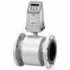
Modular pulsed DC flowmeters cover all ordinary applications within all industries. The wide variety of combinations and versions from the modular system means that ideal adaptation is possible to each measuring task and application
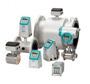
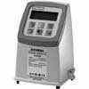
Battery-operated water meters (fully electronic) are the perfect match for drinking water applications like network distribution, revenue metering and irrigation where mains power is not available. In addition, it complies with the MID (EU) and OIML R 49 water meter standards and has the MCERTS certificate.
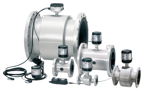
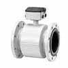
High-powered flowmeters are used for difficult applications where other flowmeters cannot stand up to the task. This flowmeter can handle liquids and heavy slurries in industries such as mining, cement and pulp and paper.
Benefits
Greater flexibility
- Wide product program
- Compact or remote installation using the same transmitter and sensor
- USM II communication platform for easy integration with all systems
Easier commissioning of MAG 5000, 6000, 6000 I
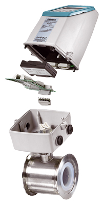
All SITRANS F M pulsed DC electromagnetic flowmeters feature a unique SENSORPROM memory unit which stores sensor calibration data and transmitter settings for the lifetime of the product.
At commissioning the flowmeter commences measurement without any initial programming.
The factory settings matching the sensor size are stored in the SENSORPROM unit. Also customer specified settings are downloaded to the unit. Should the transmitter be replaced, the new transmitter will upload all previous settings and resume measurement without any need for reprogramming.
Further, the “fingerprint” used in connection with the SITRANS F M Verificator is stored during the initial sensor calibration.
Easier service
Transmitter replacement requires no programming. SENSORPROM automatically updates all settings after initialization.
Room for growth
USM II the Universal Signal Module with “plug & play” simplicity, makes it easy to access and integrate the flow measurement with almost any system and bus-protocol and it ensures the flowmeter will be easy to upgrade to future communication/bus platforms.
Application
Electromagnetic flowmeters are suitable for measuring the flow of almost all electrically conductive liquids, pastes and slurries.
A prerequisite is that the medium must have a minimum conductivity. The temperature, pressure, density and viscosity have no influence on the result.
The main applications of the electromagnetic flowmeters can be found in the following sectors:
- Water and waste water
- Chemical industries
- Pharmaceutical industries
- Food and beverage industry
- Mining, aggregates and cements industries
- Pulp and paper industry
- Steel industry
- Power; utility and chilled water industry
The wide variety of combinations and versions from the modular system means that ideal adaptation is possible to each measuring task.
|
SITRANS F M compact installation |
||||
|---|---|---|---|---|
 |
+ |
 |
= |
 |
|
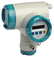
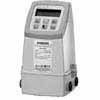
MAG 6000 transmitter |
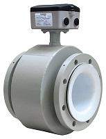
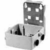
MAG 3100 sensor |
MAG 6000 compact mounted on a MAG 3100 sensor |
||
|
Example |
||||
|
Sensor |
7ME6310-3TC11-1JA1 |
|||
|
Pipe size |
DN 100 |
|||
|
Liner |
Soft rubber |
|||
|
Electrodes |
SS 316 |
|||
|
Flanges |
EN 1092-1, PN 16 |
|||
|
Transmitter |
MAG 6000, Polyamide, 115 … 230 V AC |
|||
|
Accuracy |
± 0.2 % ± 1 mm/s |
|||
|
Supply |
230 V AC |
|||
Note:
MAG 5000/6000 transmitters and sensors are packed in separate boxes, the final assembly takes place during installation at the customer’s place.
Please also see http://www.siemens.com/SITRANSFordering for practical examples of ordering.
|
SITRANS F M remote installation |
||||
|---|---|---|---|---|
 |
+ |
|
= |
 |
|
Wall bracket |
MAG 6000 |
|||
| |
+ |
 |
= |
|
|
MAG 3100 |
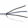
2 x cable |
MAG 3100 remote installation |
||
|
Example |
||||
|
Sensor |
7ME6310-3TC11-1AA1 |
|||
|
Pipe size |
DN 100 |
|||
|
Liner |
Soft rubber |
|||
|
Electrodes |
SS 316 |
|||
|
Flanges |
EN 1092-1, PN 16 |
|||
|
Transmitter |
7ME6920-1AA10-0AA0 |
|||
|
Accuracy |
± 0.2 % ± 1 mm/s |
|||
|
Supply |
230 V AC |
|||
|
Wall mounting kit |
FDK:085U1018 |
|||
|
Cable kit with sensor cable and electrode cable |
A5E01181647 |
|||
Technical specifications
Flowmeter Calibration and traceability
To ensure continuous accurate measurement, flowmeters must be calibrated. The calibration is conducted at Siemens flow facilities with traceable instruments referring directly to the physical unit of measurement according to the International System of Units (SI).
Therefore, the calibration certificate ensures recognition of the test results worldwide, including the US (NIST traceability).
Siemens offers accredited calibrations assured to ISO 17025 in the flow range from 0.0001 m³/h to 10 000 m³/h. Siemens Flow Instruments accredited laboratories are recognized by ILAC MRA (International Laboratory Accreditation Corporation – Mutual Recognition Arrangement) ensuring international traceability and recognition of the test results worldwide.
A calibration certificate is shipped with every sensor and calibration data are stored in the SENSORPROM memory unit.
Flowmeter uncertainty

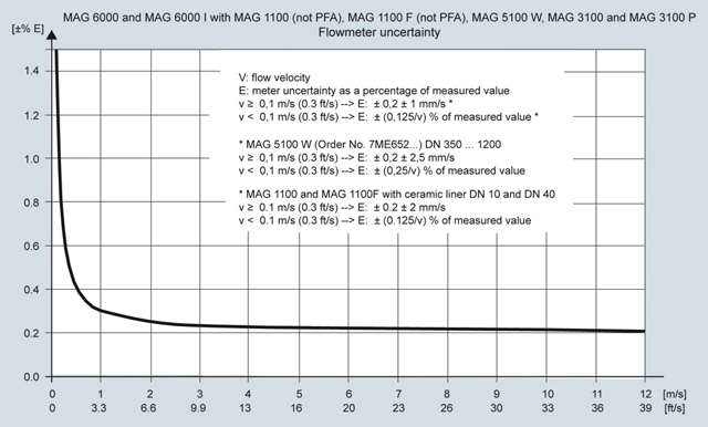
Calibration reference conditions
|
Reference conditions (ISO 9104 and DIN EN 29104) |
|
|
Temperature medium |
20 °C ± 10 K (68 °F ± 18 °F) |
|
Temperature ambient |
25 °C ± 10 K (77 °F ± 18 °F) |
|
Supply voltage |
Un ± 1 % |
|
Warming-up time |
30 minutes |
|
Incorporation in conductive pipe section |
|
|
10 x DN (DN ≤ 1200/48″) |
|
5 x DN (DN > 1200/48″) |
|
|
5 x DN (DN ≤ 1200/48″) |
|
3 x DN (DN > 1200/48″) |
|
|
Flow conditions |
Developed flow profile |
|
Additions in the event of deviations from reference conditions |
|
|
Current output |
As pulse output (± 0,1 % of actual flow +0,05 % FSO) |
|
Effect of ambient temperature |
|
|
< ± 0,003 %/K act. |
|
< ± 0,005 %/K act. |
|
Effect of supply voltage |
< 0,005 % of measuring value on 1 % change |
|
Repeatability |
± 0,1 % of actual flow for v ≥ 0,5 m/s (1.5 ft/s) and conductivity > 10 μS/cm |
|
Certificates |
|
|
Certificate of conformity, stating that the delivered parts are made of the material quality that was ordered. Available as Z option C15. |
|
Test report certificate, a non batch specific material analysis of the ordered material. Available as Z option C14. |
|
Material analysis certificate, a batch specific analysis of the material issued by an independent inspector. |
Technical specifications PROFIBUS PA/DP
|
General specifications |
|
|
PROFIBUS device profile |
3.00 Class B |
|
Certified |
No |
|
MS0 connections |
1 |
|
MS1 connections |
1 |
|
MS2 connections |
2 |
Electrical specification DP
|
Physical layer specifications |
|
|
Applicable standard |
IEC 61158/EN 50170 |
|
Physical Layer (Transmission technology) |
RS 485 |
|
Transmission speed |
≤ 1.5 Mbits/s |
|
Number of stations |
Up to 32 per line segment, (maximum total of 126) |
|
Cable specification ( Type A) |
|
|
Cable design |
Two-wire twisted pair |
|
Shielding |
CU shielding braid or shielding braid and shielding foil |
|
Impedance |
35 up to 165 Ω at frequencies from 3 … 20 MHz |
|
Cable capacity |
< 30 pF per meter |
|
Core diameter |
> 0,34 mm2, corresponds to AWG 22 |
|
Resistance |
< 110 Ω per km |
|
Signal attenuation |
Max. 9 dB over total length of line section |
|
Max. bus length |
200 m at 1500 kbit/s, up to 1.2 km at 93.75 kbit/s. Extendable by repeaters |
Electrical specification PA
|
Physical layer specifications |
|
|
Applicable standard |
IEC 61158/EN 50170 |
|
Physical Layer (Transmission technology) |
IEC-61158-2 |
|
Transmission speed |
31.25 Kbits/second |
|
Number of stations |
Up to 32 per line segment, (maximum total of 126) |
|
Max. basic current [IB] |
14 mA |
|
Fault current [IFDE] |
0 mA |
|
Bus voltage |
9 … 32 V (non Ex) |
|
Preferred cable specification ( Type A) |
|
|
Cable design |
Two wire twisted pair |
|
Conductor area (nominal) |
0,8 mm2 (AWG 18) |
|
Loop resistance |
44 Ω/km |
|
Impedance |
100 Ω ± 20 % |
|
Wave attenuation at 39 kHz |
3 dB/km |
|
Capacitive asymmetry |
2 nF/km |
|
Bus termination |
Passive line termination at both |
|
Max. bus length |
Up to 1,9 km. Extendable by repeaters |
|
IS (Intrinsic Safety) data |
|
|
Required sensor electronics |
Compact or remote mounted SITRANS F M MAG 6000 I Ex |
|
FISCO |
YES |
|
Max. UI |
17,5 V |
|
Max. II |
380 mA |
|
Max. PI |
5,32 V |
|
Max. LI |
0 μH |
|
Max. CI |
0 nF |
|
FISCO cable requirements |
|
|
Loop resistance RC |
15 … 150 Ω/km |
|
Loop inductance LC |
0,4 … 1 mH/km |
|
Capacitance CC |
80 … 200 nF/km |
|
Max. Spur length in IIC and IIB |
30 m |
|
Max. Trunk length in IIC |
1 km |
|
Max. Trunk length in IIB |
5 km |
PROFIBUS parameter support
The following parameters are accessible using a MS0 relationship from a Class 1 Master.
MS0 specifies cyclic Data Exchange between a Master and a Slave.
|
Cyclic services: |
||
|---|---|---|
|
Input (Master view) |
Parameter |
MAG 6000/MAG 6000 I |
|
Mass flow |
||
|
Volume flow |
✓ |
|
|
Temperature |
||
|
Density |
||
|
Fraction A1) |
||
|
Fraction B1) |
||
|
Pct Fraction A1) |
||
|
Totalizer 1 |
✓ |
|
|
Totalizer 22) |
✓ |
|
|
Batch progress2) |
✓ |
|
|
Batch setpoint |
✓ |
|
|
Batch compensation |
✓ |
|
|
Batch status (running …) |
✓ |
|
|
Output (Master view) |
Set Totalizer 1+2 |
✓ |
|
Set Mode Totalizer 1+2 |
✓ |
|
|
Batch control |
✓ |
|
|
Batch setpoint |
✓ |
|
|
Batch compensation |
✓ |
1) Requires a SENSORPROM containing valid fraction data.
2) Value returned is dependent on the BATCH function.
When ON, Batch progress is returned.
When OFF, TOTALIZER 2 is returned.
Flow and speed chart
Metric
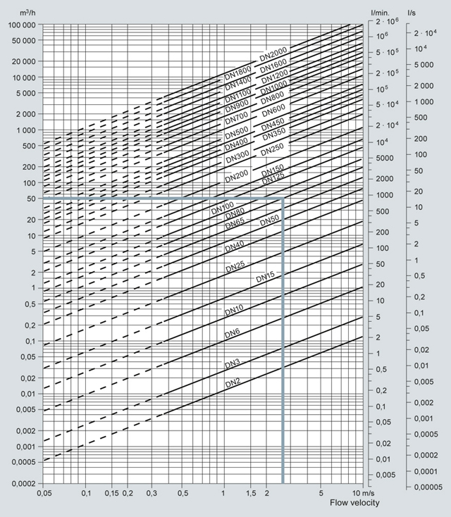
Sizing table (DN 2 … DN 2000)
The table shows the relationship between flow velocity v, flow quantity Q and sensor dimension DN.
Guidelines for selection of sensor
Min. measuring range: 0 … 0.25 m/s
Max. measuring range: 0 … 10 m/s
Normally the sensor size is selected so that nominal flow velocity v lies within the measuring range 1 to 3 m/s.
Example:
Flow quantity of 50 m3/h and a sensor dimension of DN 80 gives a flow velocity of 2.7 m/s, which is within the recommended measuring range of 1 to 3 m/s.
|
Flow velocity calculation formula |
Units |
|
v = 1273.24 · Q/DN2 or |
v: [m/s], Q: [l/s], DN: [mm] |
|
v = 353.68 · Q/DN2 |
v: [m/s], Q: [m³/h], DN: [mm] |
Link to “Sizing program”:
https://pia.khe.siemens.com/index.aspx?nr=11501
Imperial
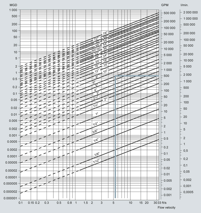
Sizing table (1/12″ … 78″)
The table shows the relationship between flow velocity v, flow quantity Q and sensor dimension size.
Guidelines for selection of sensor
Min. measuring range: 0 … 0.8 ft/s
Max. measuring range: 0 … 33 ft/s
Normally the sensor size is selected so that nominal flow velocity v lies within the measuring range 3 to 10 ft/s.
Example:
Flow quantity of 500 GPM and a sensor dimension of 6″ gives a flow velocity of 5.6 ft/s, which is within the recommended measuring range of 3 to 10 ft/s.
|
Flow velocity calculation formula |
Units |
|
v = 0.408 · Q/(Pipe I.D.)2 or |
v: [ft/s], Q: [GPM], Pipe I.D.: [inch] |
|
v = 283.67 · Q/(Pipe I.D.)2 |
v: [ft/s], Q: [MGD], Pipe I.D.: [inch] |
Link to “Sizing program”:
https://pia.khe.siemens.com/index.aspx?nr=11501
Installation conditions
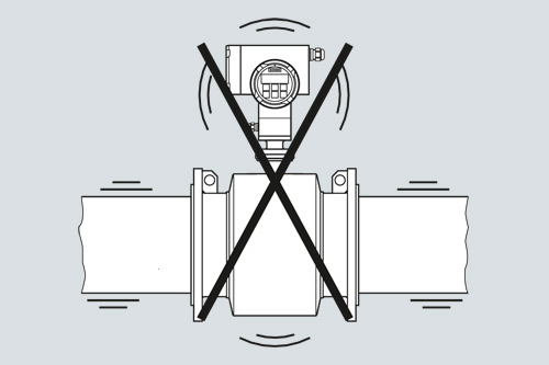
Vibrations
Strong vibrations should be avoided.
In applications with strong vibrations, remote mounting of the transmitter is recommended.
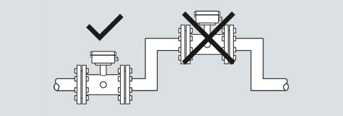
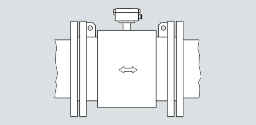
The sensor must always be completely filled with liquid.
Install in pipelines which are always full
The sensor must always be completely filled with liquid. Therefore avoid:
- Installation at the highest point in the pipe system
- Installation in vertical pipes with free outlet
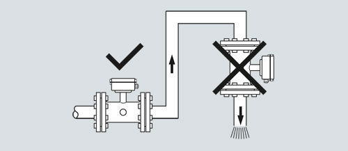
Do not install in pipelines which can run empty
For partially filled pipes or pipes with downward flow and free outlet the flowmeter should be located in a U‑Tube.
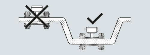
Install in U-tubes when pipe is partially filled
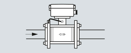
Installation in vertical pipes
Recommended flow direction: upwards. This minimizes the effect on the measurement of any gas/air bubbles in the liquid.
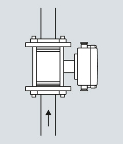
Install in vertical pipes with upward flow direction
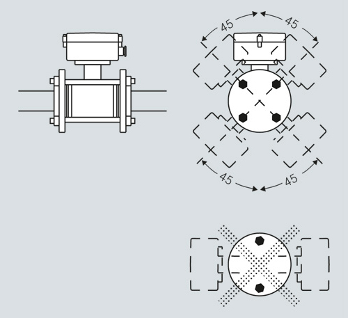
Installation in horizontal pipes
The sensor must be mounted as shown in the below figure. Do not mount the sensor as shown in the lower figure. This will position the electrodes at the top where there is possibility for air bubbles and at the bottom where there is possibility for mud, sludge, sand etc.
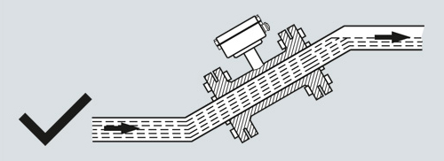
Measuring abrasive liquids and liquids containing particles
Recommended installation is in a vertical/inclined pipe to minimize the wear and deposits in the sensor.
Install in vertical pipelines with upward flow direction if measuring abrasive liquids
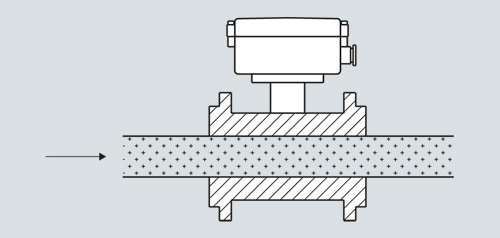
Inlet and outlet conditions
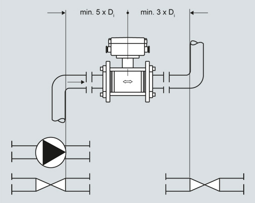
Installation between elbows, pumps and valves: standard inlet and outlet pipe sections
To achieve maximum accurate flow measurement it is essential to have straight length of inlet and outlet pipes and a certain distance between the flowmeter and pumps or valves.
It is also important to center the flowmeter in relation to pipe flange and gaskets.
Ambient temperature-Installation
Temperature changes can cause expansion or contraction in the pipe system. To avoid damage on the sensor use of proper gasket and torque should be ensured. For more information see sensor instruction.
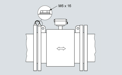
Potential equalization
Potential equalization
The electrical potential of the liquid must always be equal to the electrical potential of the sensor. This can be achieved in different ways depending on the application:
- Wire jumper between sensor and adjacent flange (MAG 1100, MAG 3100)
- Direct metallic contact between sensor and fittings (MAG 1100 F)
- Build-in grounding electrodes (MAG 3100, MAG 5100 W)
- Optional grounding/protection flanges/rings (MAG 1100, MAG 3100, MAG 8000)
- Optional graphite gaskets on MAG 1100 (standard for MAG 1100 High Temperature)
- MAG 8000 installed in plastic or coated pipes: two grounding rings to be used.
Grounding
MAG 3100 and MAG 5100 W: with grounding electrodes in conductive and non-conductive pipes (no further action necessary)
MAG 1100 and MAG 3100; without grounding electrodes in conductive pipes (MAG 1100 use graphite gasket)
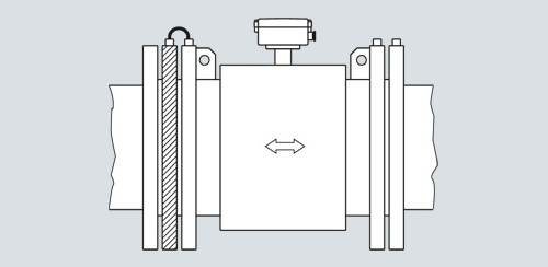
Without grounding electrodes in non-conductive pipes use grounding ring(MAG 1100 use graphite gasket)
MAG 1100 F grounding via process connections. MAG 8000 grounding see MAG 8000 pages.
Vacuum
Avoid a vaccum in the measuring pipe, because this can damage certain liners.
Installation in large pipes
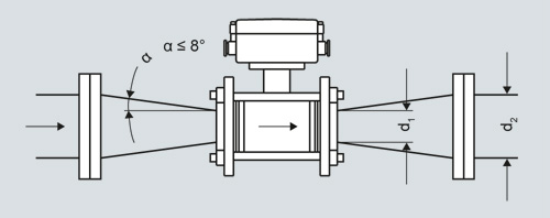
Reduction in nominal pipe diameter
The flowmeter can be installed between two reducers (e.g. DIN 28545). Assuming that at 8° the following pressure drop curve applies. The curves are applicable to water.
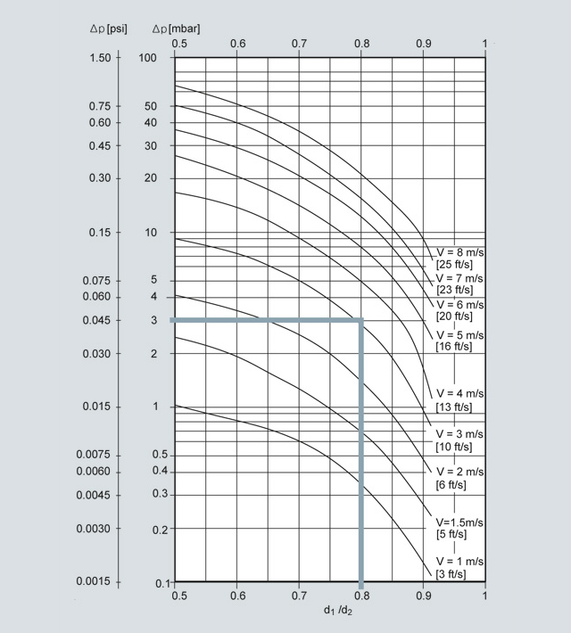
Pressure drop as function of diameter reduction between reducers
Example:
Flow velocity (v) of 3 m/s (10 ft/s) in a sensor with a diameter reduction DN 100 (4″) to DN 80 (3″) (d1/d2 = 0.8) gives a pressure drop of 2.9 mbar (0.04 psi).
Ambient temperature
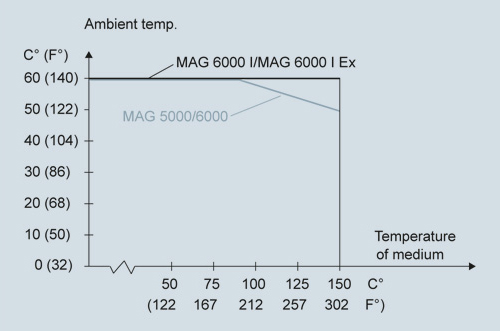
Max. ambient temperature as a function of temperature of medium
The transmitter can be installed either compact or remote.
With compact installation the temperature of medium must be according to the graph.
Sensor cables and conductivity of medium
Compact installation:
Liquids with an electrical conductivity ≥ 5 μS/cm.
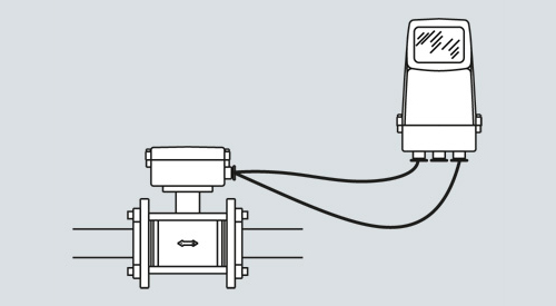
Remote installation
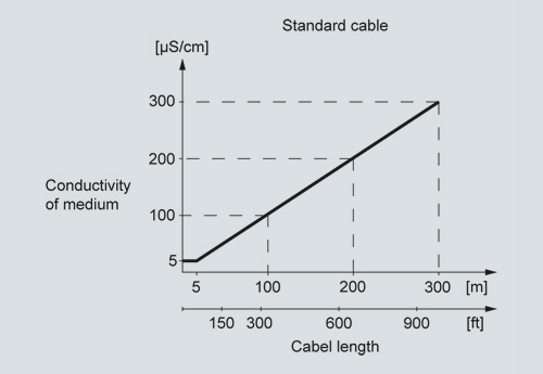
Minimum conductivity of medium (using standard electrode cable)
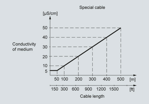
Minimum conductivity of medium (using special electrode cable)
Empty pipe detection
The installation has to fulfill the following limitations for usage of the empty pipe detection function:
- media conductivity ≥ 20 μS/cm
- length of cable at remote installation ≤ 50 m (150 ft)
- special shield cable must be used
Note for MAG 1100 sizes DN 2 and DN 3:
- empty pipe detection is not available
- the media conductivity must be ≥ 30 μS/cm
Note for MAG 5000/6000 CT (FW 3.03):
- empty pipe detection is not available